We write code, that writes code.

The DRWNG CODE solution is an industrial eco-system of software applications promoting IEC 63131

Together those tools promote an engineering workflow for the delivery of Safety Automation System (SAS) running on the Norwegian continental shelve’s offshore installations. The AML model is put at the heart of the workflow acting as the common file export format in between software tools throughout the entire lifecycle of a plant, for the benefit of engineering service providers, plant constructors, plant operators and manufacturers.

The technology is developed by EATOPS and its partners against the IEC 63131
and Norsok I-0005.

 
AutoGen-laser.png

The toolbox is production ready

The Automated Workflow was developed in line with the IEC 63131 standard to fasten the engineering specification phase, consolidate the project tag database and promote automatic code generation for the PLC / HMI code.

 
  • Run as a Cloud Based Service

  • Runs on VMWare instances

  • Web-based or Windows desktop compatible


The basic motive of the DRWNG Code platform is cost savings & accuracy. Cost-saving is always on the mind of the customer of industrial automation. In our highly developed economies, the cost of skilled labour is most of the time far more significant than material or equipment cost. Nevertheless, all too often engineers are confronted with a situation where they have no possibility to reuse the results of their fellows.


A lack of open interconnection between engineers in an automation project leads to exploding costs. Caused by a fragmented documentation and tool landscape, this complex is the cause of many failed project and hampers the growth of future markets in automation significantly.
The DRWING Code workflow is a revolution for the industrial automation because by actively promoting and standardized workflow and file echange format, it is a door opener for a new generation of control systems with an unprecedent level of precision and software logic.


The workflow is based on a data model governed by the IEC 63131 using an AML or JSON file as a file format between the different applications.

Automation Engineers should install the follow applications onto their desktop computers (below).

Sequence Builder, SCD Builder are commercialized under the following product codes SEQ001, SEQ002 (optional), SEQ003 (optional), SCD001, SCD002 (optional), SCD003 (optional).

 
workflow.PNG

Workflow toolbox user guide (sequence, SCDs and more…)

1. Introduction

This is the end-user manual for the SCD / Sequence toolbox. It explains how to use the features of the toolbox using the "regular GUI". Please note that, on top of that, the end-user is assumed to know and follow the project guidelines (especially naming conventions and iec 63131 standard graphical representations of SCD and Sequences).

2. Features in this toolbox

- Read sequences defined using the Sequence Builder or Sequence Builder for Excel

- Produce Visio and PDF documents representing the sequences, following NORSOK I-0005 or iec 63131 standard (with some extra features)

- Generate SFC charts of the sequences in Simatic SFC editor ("smart keyboard")

- Generate SCL code for the sequences compatible with Siemens 400 and 1500 series. (as well as SCL code for Scheduler activities and config file for Scheduler GUI)

- Generate Symbol Table entries for Function Blocks drawn in Simatic CFC editor

- Extract the list of tags used in SCDs

- Export to your SCD or Sequence to AML (Automation Markup Language)

3. Tutorials

3.1. How to draw sequences in Sequence Builder?

Sequence Builder (product code SEQ 001)

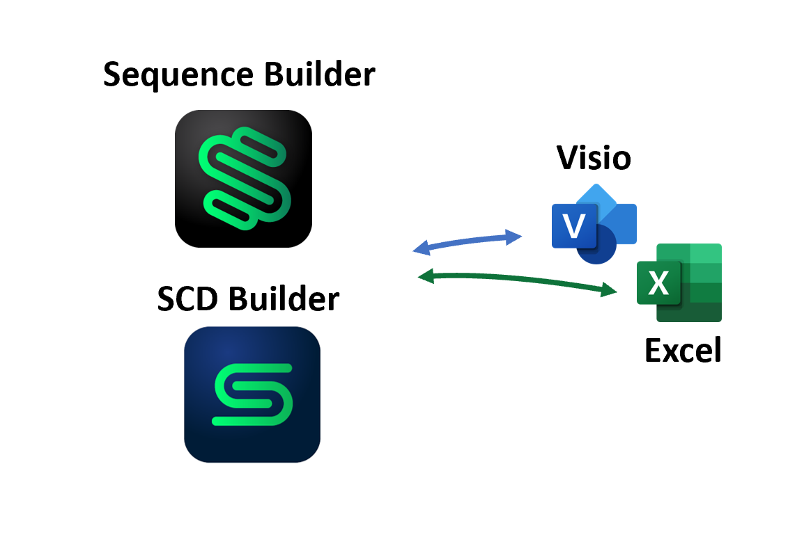
Sequence Buidler is a computed assisted drawing software CAD for the drawing of automation sequences. The engineers is assisted when calling for engineering tags, following the IEC-63131 standard.
Adding a new step or condition has never been easier, the snapping features allow a considerable time reduction during the drawing of a sequence. Click add STEP or add CONDITION to modify the existing drawing.

Sequence Builder natively supports references to SCD drawings which are perfectly synchronized when updating the sequence. The positioning of every box is automatic. No waste of time since the layout is completely managed for you.


3.2. How to write sequences with the Excel template

*Remark about template version* : be sure to always use the latest version of the Excel template (currently version 5). The version number can be checked in all sheets in the C1 cell. The tool is able to process versions 4 and 5 only, older versions shall be converted to the newest template before being used in the tool.

Here are the important points to follow when creating an Excel description of sequences :

- Start by opening the latest template file (sequence_template_with_example_and_comments.xlsx)

- Learn about the different constructions that you can use, as shown in the "example_sequence" sheet:

- Instructions in the file (cells M11 and below) and comments on the right side (cells Y55 and below) explain the general rules that shall be followed when writing a sequence, as well as a description of the different choices available in the drop-down lists.

- If you want to write a sequence with parallel and/or alternate branches, explanations in cells Q43 and below explain how to fill the dedicated header for non-linear sequences.

- The main part of the sheet (lines 57 and below) show the accepted patterns that you can use to add a step (including empty steps), a transition (including empty transitions), documentation-only conditions for KB block, loop backs, gotos and separation of START/STOP sequences. Be sure to follow the patterns when you fill the file, otherwise this will lead to parsing errors.

- To start writing you own sequence, copy the "empty_sequence" sheet in a new workbook, save it under the name of your choice (follow project guidelines) and start by filling the header. Special care has to be taken when filling some of them:

- `Drawing number` (cell C5) : it is the name written in the document frame when generating a Visio document, as well as the name of the SFC chart when generating it.

- `Sequence number` (cell N3)

- `KB block tag reference` (cell N5) : since most of the time (or all the time ?) there is no SCD drawing where the KB block for a given sequence appear, it is necessary to prefix the KB block name with the PLC node number that will execute the sequence. For instance, if sequence 123 - represented by 07-KB-0123 - is executed on node D20, you must write `D20:07-KB-0123` in this field. This is important for SFC generation.

- You can write several sequences in the same Excel file, simply copy the "empty_sequence" sheet several times from the template.

- If you need to add sub-sequences (for non-linear sequences), also copy the "empty_subsequence" sheet in your new workbook (one sheet per sub-sequence).

- If you have quite a lot of sub-sequences and this makes your Excel file difficult to read, you can add an extra sheet called "Overview" (do not use any other name) where you can describe with a diagram how your file is organized. There is no template for this as it is just intended for file documentation. See the following capture for an example :

- Now, you can edit the main part of the sequence. In order not to break the template, be sure to follow these rules when editing the file:

- Never modify grey cells

- Use only paste values functionality in Excel to avoid erasing the conditional formatting and drop-down configurations. See the following capture.

pasteValuesInExcel.PNG

- NEVER paste ranges that overlap grey columns or you will break the template. Only exception: you can paste in the center "Comment" column (column N) with "paste values" even though there are grey cells between the white cells.

- In general, avoid inserting and removing lines, because this will also break the template; if you really need to do so, here is how to fix the template after this operation:

- Select an entire empty line that was not affected by your insertion/removal operation (from column A to column W)

- Fix the formulas and drop down config (NB: this time use real copy pasting or Excel drag-and-copy feature) :

- For line insertion : duplicate the selected line on the newly inserted lines

- For line deletion : duplicate the selected line on the line following the last removed line

- Fix the conditional formatting :

- Open Home > Conditional Formatting > Manage Rules.

- Select "This Worksheet" in the "Show formatting rules for" drop down list.

- Delete any duplicate rule that only applied to single lines and only keep the two rules as shown in the following screenshot (one grey, one red)

conditionalFormattingFix.PNG

- Change the "Applies to" field to make it identical to the screenshot

- `=$N$57:$N$430` for the grey rule

- `=$P$57:$W$430,$A$57:$K$430` for the red rule

- Click Ok to validate

- You're done fixing the template. As you see, the procedure is quite heavy so try to avoid inserting and deleting lines too often ;-)

3.3. Convert Microsoft Excel/Visio representation to JSON/AML

Procedure

The workflow toolbox is using a specific file format to represent the input data for most of its features. We simply call them "JSON files", although technically JSON is just the name of the format.

*Remark* : this format is "human readable", unlike Visio and Excel formats, and it only contains the useful information for the workflow tool. However, is is usually big enough to be difficult to read, thus we do not advise to look inside.

To convert Visio and Excel formats into JSON, use the "Visio, Excel to JSON" tab and add your files in the list. Check the ones you want to convert and click "Create JSON representation of selected files"

JSON files will be created in the same folder as the originals, their .vsdx or .xlsx extension being replaced with .json.
An export to AML (Automation Markup Language) is also supported.

conversionToJsonTab.PNG

Tips

- Be sure to check the output log (in the bottom half of the GUI) for errors while parsing the files. Common errors are:

- For Visio files:

- Incorrect frame : if you use an old version of the frame, you must manually update to the newest version to be able to fully convert your SCD/Sequence.

- Badly connected lines : if a connector end point is not properly connected to an object, you will get this error. For now, you can ignore it for most connectors but not for General Signals, as this may prevent the toolbox to check your signal connections.

- For Excel files:

- Not leaving an entirely blank line between steps and transitions, or leaving more than 10 blank lines

- Incoherent references in the "non-linear" headers. These one are quite difficult to spot. Be sure to re-read your file thoroughly before you try the conversion again. You are also encourage to use an "Overview" sheet if the file is quite big, to explain its structure with a simple diagram.

- Do not forget to re-convert your files to JSON every time you modify the originals. There is an "Overwrite existing JSON files" checkbox that you can use for that purpose. (Spoiler alert : another GUI that is able to track the changes and regenerate the appropriate files is on its way... be patient!)

- The file list is saved when exiting the program so you do not have to re-do the whole procedure every time. Just check the files you want to re-convert and go!

3.3. Generate Visio & PDF documents for sequences

Visio files are generated using the following tab :

sequenceVisioGeneration.PNG

Prerequisites

You need Sequence Builder, SCD Builder, and/or Visio installed on your computer as well as SCD Builder for Visio and Sequence Builder for Visio and Sequence Builder for Excel, available [here] (http://apps.eatops.com/). Open & close Visio before launching the workflow tool to ensure you are using the latest version (the auto-update will download and install it for you if necessary).


Procedure

- Generate the .json files for your sequences from their Sequence Builder / SCD Builder or Excel or Visio files, using the procedure described in [Convert Excel/Visio representation to JSON](#32-convert-excelvisio-representation-to-json).

- Add the .json files containing your sequences in the top-left file list.

- Check the files you want to load in the tool and press "Load sequences from selected files". The sequences appear on the top-right panel.

- Check the sequences you want to generate, input the path where you want the Visio files to be generated in the `Output folder` field and press the "Generate Visio files for checked sequences" button.

- Be patient ! Visio will open and close once per sequence and you will not be able to see the sequence while it is generated. You can monitor the progress by looking at the two progress bars at the bottom of the window: the top one indicates the progress in the current file, the bottom one indicates the global progress. You can cancel with the Cancel button, this may take a few seconds before actually cancelling.

Remarks

A few known limitations:
-For large sequences/SCD and high performances, use Sequence Builder and SCD Builder instead of Visio. Microsoft Visio shows performances issues on large A1 or A0 file format.

- The current version of the toolbox does not generate the KB block inputs on the Sequence Start as they should.

- The Start and Stop sequences are not separated in two sequences as they should.

3.4. Generate SFC charts from sequences

SFC charts are generated from the following tab:

sequenceSfcGenerationTab.PNG

Prerequisites

Simatic Manager shall be installed on your computer, with SFC editor available. The toolbox only supports SFC Editor version K9.0.1.0. Simatic Manager must be opened before trying to generate anything.

*NB* : on some computers, it is required to launch the toolbox with admin rights in order to be able to connect to Simatic Manager. Simatic Manager in itself shall NOT be launched with admin rights (severe crashes have occurred in the past, be careful)

Procedure

- Generate the .json files for your sequences AND the .json files contains the SCDs related to the sequences from their Excel and Visio files, using the procedure described in [Convert Excel/Visio representation to JSON](#32-convert-excelvisio-representation-to-json).

- Add the .json files containing the sequences AND the .json files contains the SCDs related to the sequences in the top-left list and press "Load selected files". The sequences will appear on the top-right corner.

- Carefully read the log messages to check if the links between sequences and SCDs are correctly found. In the above screenshot, you can see that PLC nodes (of Function Blocks in SCDs) for some sequence conditions and actions could not be found. This will not prevent the sequence from being generated but if the tool cannot find a given reference on a SCD, it cannot figure out whether the block corresponding to the sequence condition or action is located on the same PLC or if it has to generate a communication tag. By default, as mentioned in the warning message, it will assume that the missing blocks execute on the same node as the sequence itself. Also see the remark concerning PLC node number in the "How to write correct sequences with the Excel template" section.

- Select the sequences you want to generate on the top-right panel.

- Fill in the "Simatic project parameters" panel:

- *NB* : parameters are saved when you exit the application, so you do not have to re-enter them every time. They are not saved if the application crashes (which can happen if the configuration is not correct) so be sure to exit/reopen the toolbox when you make changes.

- `Project Path` shall be pointed to the folder containing Simatic project. It must be exactly as shown in Simatic Manager window title. In case of a multiproject, the project path must not be the path of the multiproject itself but the path of the project where the SFC has to be generated. See the below screenshot of Simatic Manager for an example: here we want to generate inside D20_DFMCS project located in VESSEL multiproject, so the project path is the one containing D20_DFMCS project. **The project path does not necessarily end with the name of the project.**

- Check "Project is located in a multiproject" if relevant.

- `Program Path` is the path of from the root of the project tree view (left panel of Simatic Manager) to the program folder where the charts have to be generated. Separate each level with a backslash. In the below example, to generate inside the selected "S7 Program(26)", one must enter **exactly** `VESSEL\D20_DFMCS\D20 DFMCS\CPU 416F-3 PN/DP\S7 Program(26)` in this field. Spaces, underscores, hyphens, case, forward slashes, backslashes must be respected.

SimaticForSfcGenerationWithComments.png

- `Generated SCL code output path` field is ignored for SFC generation.

- As mentioned in the reminder section on the "Action" panel:

- Ensure Simatic Manager is opened

- Ensure the project where to generate is opened and that there is no other project with the same name visible in the "File > Manage" menu of Simatic Manager. If there are multiple projects with the same name, you must hide the unused ones (this does not remove them from the hard disk but just hides them from this list)

- Ensure that SFC Editor opens with a maximized chart window (the window inside the SFC editor, not the editor itself). If there is no chart in the project, just create a dummy one and ensure it is maximized. If you overwrite existing charts, they should also be maximized before closed.

- Close all applications that could interfere with the mouse, keyboard, window focus during the whole generation process.

- If you want to regenerate (overwrite) existing charts with their new contents, check the "Overwrite existing SFC charts", otherwise leave unchecked. If unchecked, existing charts with the same name as the selected ones will not be erased nor overwritten.

- Click on "Generate SFC for selected sequences"

- Be patient ! SFC generation takes quite a while. You can monitor the progress by looking at the two progress bars at the bottom of the window: the top one indicates the progress in the current sequence, the bottom one indicates the global progress. You can cancel with the Cancel button, this may take a few seconds before actually cancelling.


Nota bene:

When generating a SFC chart, contents from the column Drawing#, Tag and Suffix are combined together to generate the code that accesses (read or write) a variable in the PLC.

It is assumed that the blocks to be accessed are located in a CFC chart which name corresponds to the Drawing# column and that they have an extra "SFC_In" input reserved to connect SFC charts.

If this "SFC_In" input is not present, you must add a single asterisk * at the end of the suffix column, to let the generator know about it. It is then recommended to add a note to explain the meaning of the asterisk mark.

Example:

1 | N | 06-NU-8510_SEL | .Sel_In2 * | some comment | | P-AOG-I-0078-001 will produce:

IP-AOG-I-0078-001/06-NU-8510_SEL.Sel_In2 := 1

and

1 | N | 06-NU-8510_SEL | .Sel_In2 | some comment | | P-AOG-I-0078-001

will produce:

IP-AOG-I-0078-001/06-NU-8510_SEL.SFC_In.Sel_In2 := 1

3.5. Generate symbol-tables for CFC chart blocks

Introduction

When creating a CFC chart in the CFC editor, function blocks inserted in the chart are created as instances using only absolute addressing (i.e. the block instance DB has just a number, say DB176 instead of a name like "07-HV-1234"). This number is attributed by Simatic when first compiling the chart and may change in some circumstances when blocks are updated.

This prevents publishing the block IDB in OPC for instance or using it in HMI system because they both require a symbolic name.

When editing the chart, a block name is given. This tool is able to retrieve it from the SCL source code that Simatic generates and add corresponding entries in the Symbol table.

The symbol table can be updated with the following tab:

cfcSymbolicNameTab.PNG

Procedure

- Open Simatic Manager and the project containing the charts from which the tags should be extracted.

- Ensure the project that there is no other project with the same name visible in the "File > Manage" menu of Simatic Manager. If there are multiple projects with the same name, you must hide the unused ones (this does not remove them from the hard disk but just hides them from this list)

- Navigate to the charts folder and recompile it:

- Right click > Compile (or Ctrl + B)

- Ensure "Generate SCL source" checkbox is checked, see screenshot

cfcSymbolicNameCompileStep.PNG

- Close all instances of CFC & SFC editors, as well as Symbol Table editor.

- Input the parameters in the toolbox tab:

- `Project Path` : the full path of the project containing the charts (the folder containing the .s7p file), as written in Simatic Manager window title (see [Procedure for generating SFC charts](#procedure-2) about how to write the path in case of multiprojects)

- `Project Name` : project name (in case of multiproject, this is **not** the name of the multiproject, again see [Procedure for generating SFC charts](#procedure-2) for details).

- `Program Name` : the name of the program containing the charts. It must be the parent folder of the Charts folder, with a name like "S7 Program(xyz)"

- `Source Name` : name of the SCL source generated by the compilation of the charts folder. Normally, it should be "@SCLFileFromCFC_SFC_1", please double check in the "Sources" folder.

- Press the "Generate symbolic names" button.

- The symbol table will be updated, and the log on the bottom part of the toolbox window indicates which tags were added, updated or removed.

Troubleshooting:

- If you get access rights error when pressing the button, please try again by running the toolbox with Admin rights.

3.6. Listing tags

The toolbox is able to generate a CSV file containing all the tags from all the SCDs. This can be done in the following tab:

tagListTab.PNG

Procedure

- Add all the .json files representing the SCDs that you want to use for tag extraction and check them.

- Fill in the `Tag List file (output)` with a filename where the tag list shall be exported.

- Press the "Export tag list for selected files" button. The log shows warning for duplicated tags (oyu will also find them duplicated in the CSV output)

Troubleshooting

- The generated CSV file can normally be opened in Excel directly but if you get all the fields in the same column, try importing the CSV file using the "Data > From Text" function in Excel and choose "comma" as column delimiter.

- If some of the SCDs have a wrong frame (old version) or no frame, some of the columns will be empty. The only way to get them correct is to fix the corresponding files, re-convert them into JSON format, and re-run the tag export function.

3.7. Validate new tags

It is a challenge to predict exctly how many tags will be required in the early engineering phase and even the later project specification phases. This need for new tags could happens and this ‘validate-new-tag’ feature is here to remove the burden of the red-tape needed to get a new tag accepted & available immediately.

As soon as an engineer requires a new tag, the tag request is placed directly into the SCD or sequence source files by adding the character “?” followed by the new tag request. For instance to request the new tag 123-ABC-456, the engineer should fill-up his function with the tag ?123-ABC-456

The tag request triggers an internal approval cycle involving the project lead engineer. As soon as his tag request is approved, all involved documents will be synchronized and updated using the newly accepted tag.

3.8. Generate Scheduler activity SCL code & config files

Prerequisites

You need TIA Portal version 15.1 installed on your computer to be able to import the SCL files and compile them. If you plan to use the auto import/compile/download features, you also need TIA Openness installed (comes with TIA installer and installed by default).

You will also need the Scheduler HMI program and the Scheduler Core program to be able to run sequences.

Procedure

- The top-left and top-right panels are used the exact same way as in [Generate SFC charts from sequences](#34-generate-sfc-charts-from-sequences). Please refer to these explanations. Note that here also JSON representation of SCDs related to the base activities sequences have to be added in the list.

- Fill in the "Generation parameters / TIA project parameters" panel:

- `Generated SCL code path` is where the SCL files will be generated. It is the only mandatory parameter.

- If you want the toolbox to automatically insert the generated files in TIA project as well as compile and download to the PLC, you also have to fill in the following three parameters:

- `TIA project filename` : browse to the .ap15_1 file of the Scheduler TIA Portal project.

- `Device name in TIA project` : the is the name of the device (PLC) in TIA tree view. It is already set up as "SeqCtrl" by default, change it here as well if you rename the device in TIA Portal.

- `PC Interface name for download from TIA` : name of the PC/PG interface used to communicate with the PLC. (only necessary if the "Download to PLC after compilation" option is checked) This parameter is quite nasty to get right, it is actually the full name of the network card used to communicate with the device. One way to find it is to look into the Network Connection settings in Windows Control Panel, as shown in the following screenshot:

networkConnections.PNG

Here two cards are available: one real card and one used for PLCSIM.

- Open TIA portal and the Scheduler project if at least one of the checkboxes under "Generate SCL code" is checked. As mentioned in the reminder, try to go online then offline to ensure that TIA is able to communicate with the PLC (virtual or not).

- Press the "Generate SCL code" button. If auto import/compile/download in TIA options are selected, TIA will display a dialog asking for approval before the toolbox can take control of it.

Troubleshooting

- If the generated code does not compile because the generated tags are incorrect, double check the Excel file for typos. If the error comes from wrong implementation in other parts of the PLC code, it is possible to add naming convention exceptions in a namingExceptions.json file located in the same folder as the scdtools.exe. It shall just contain a mapping of the form :

~~~~JSON

{

"\"TagDB1\".Tag1CompliantWithNamingConvention.Suffix" : "\"TagDB2\".My_tagNOTCompliant__with_Convention.xSuffix",

"\"TagDB1\".Tag2CompliantWithNamingConvention.Suffix" : "\"TagDB2\".other__non__COMPLIANTTAG.MYBUTTONpressed"

}

~~~~

3.9 Live Sequence Viewer

Continuous testing of the sequence diagrams is made possible using the ‘online mode’. When connected to the live simulation the engineer is able to test and troubleshoot the execution of the sequence from a very early stage. The live-data will reveal problems such as a non-existing tag, or a wrong condition.

Export the Sequence towards Live Sequence Builder- LSV.

Extracted from Live Sequence Viewer - Bulk Transfer sequence


4. Alarm Configuration

The SCDs allows for alarm thresholds configuration. For example, let’s take the case of a level transmitter variable, its Min/Max values are defined directly inside the specification document (SCD) and imported as part of the JSON model. Those set-up points triggering the alarms will then be available to the HMI software package to visualize alarms of different level of severity, priorities. It is also possible to configure the dedicated alarm messages.


Last updated on Dec 1st 2021.


color-3.png
 
 
equipment list.PNG

Contact

color-3.png